Visualizing the residual log shift
On the context menu of Blocked wells you have the option to select Create All Residual Log Shift Logs. (Blocked wells are a grid item, auto-created when upscaling a log and stored under your 3D Grid in the JewelExplorer). Select this option if you want to investigate whether mismatches exist in your model between well markers and the tops or bases of zones, to which the well log data is upscaled.
During creation of the 3D grid, markers are used as a framework to define the zones in the grid, so in principle the well markers in your model coincide with the grid zone tops and bases. However, there are situations in which a well marker cannot be exactly honored in the 3D grid, for example, when two well markers with different depths, but representing the same event, are too close together, or even intersect the same grid cell. Also, bad well datum is a possible cause. In those situations, only one of the two well markers can be honored. The other well marker will have a slight mismatch with the top or base of the grid zone. This (however small) mismatch becomes important during well log upscaling, where it is important that the log record is exactly divided (during upscaling) at the well marker depth, and not at the top or base of the grid cell, which would result in log data to be included in the wrong (adjacent) grid cell.
To capture such discrepancies, a 'shift' is performed, slightly moving the marker (and at the same time stretching or squeezing the well log data) to match the grid cell top/base, ensuring that the correct log values are included during upscaling. Select Create all residual log shift logs from the context menu of your Blocked wells in the JewelExplorer to see whether shifts are performed in your model during well log upscaling. The log shows the difference between markers and the corresponding grid cell intersections as a Depth value, and can be visualized in the Well View. If substantial log shift values are calculated, a possible solution could be to redo the well matching and re-generate the grid, for instance, with a smaller lateral grid cell size.
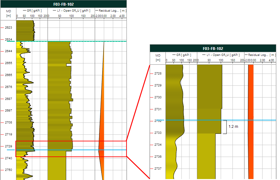
The image on the left shows an overview of the well log correlation with a residual log shift log. The tracks show, from left to right: The raw log, the corresponding upscaled log and the residual log shift log. Around depth = 2635 m, the residual log shift log equals 0. The grid cell boundary coincides with the well marker. In the next interval at around depth = 2733 m, the residual log shift log shows a peak to the left. The grid cell boundary does not coincide with the well marker.
On the right, the display has zoomed in on the highlighted interval. The difference between the marker (thin blue line) and the base of the upscaled interval (the base/top of a grid cell) amounts to 1.2 m (in this well). The residual log shift log has a value of -1.2 m. The log data is now stretched (or squeezed) over this distance so that the correct log data is used (the well marker is honored) during upscaling. Note that it is important that the log shift value is small. If it is large, redo the well matching and re-generate the grid, for instance, with a smaller lateral grid cell size.